Selection Criteria and Calculations
For every application you must determine
the required TORQUE and SAFE OPERATING RPM.
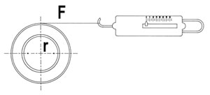
Torque (T) lbs. in. = Force (F) lbs. X Radius (r) in.
Note: Force often is the tension.
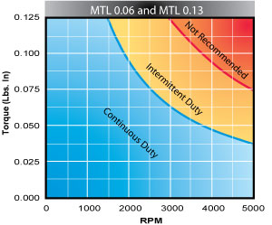
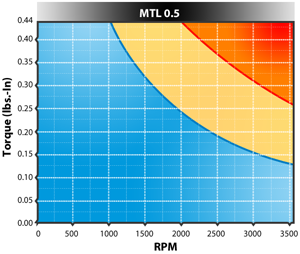
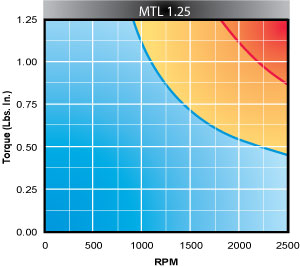
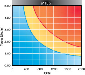
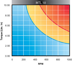
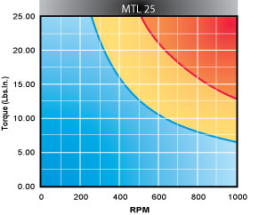
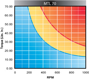
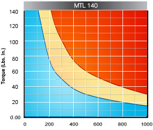
Operating Curves:
When you turn the rotor of a magnetic clutch, you convert mechanical energy into thermal energy (watts). The amount of thermal energy (watts) is a function of the RPM and the TORQUE SETTING.
How To Use Charts:
Find the slip RPM on the X axis and the torque on the Y axis. The BLUE area represents safe continuous duty. The area between the two curves (YELLOW) represents intermittent duty. Example is 5 minutes on, 5 minutes off. Operating in the RED zone for any period of time will cause overheating and could damage the unit.
| Operating Curves | |
 |
 |
 |
 |
 |
 |
 |
 |
 |
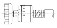
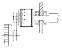
| Typical Mounting | ||
| As a Coupling: | As a Clutch: | As a Pay-Off Brake: |
 |
 |
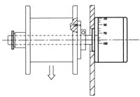 |
| For load protection or torque limiting, the clutch is fitted onto the motor shaft and connected via a flexible coupling to the load. | The clutch housing is driven by a belt or chain and the rotor connected to the load. Shown here is a small custom adapter on the housing. | For relatively light loads, a shaft can be fitted to the rotor and a small spool of material directly payed off. |